
In this tutorial, you’ll learn how to use an ESP32 board to control an LED with a pushbutton. It’s a simple and useful project to get familiar with how the ESP32 interacts with basic electronic components.
By the end of this guide, you’ll know how to detect button presses and turn an LED on or off — a foundational skill that opens the door to building interactive hardware projects.
What You’ll Learn
- How to read the state of a digital input (pushbutton)
- How to control a digital output (LED)
- How to wire a simple circuit on a breadboard
- How to write and upload code to the ESP32
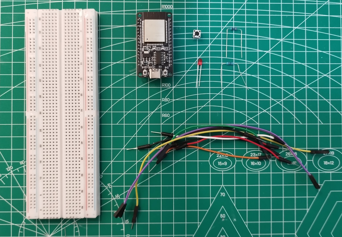
Parts Required
To follow along, you’ll need the following components:
| Component | Quantity |
| ESP32 DOIT DEVKIT V1 | 1 |
| 5mm LED | 1 |
| 220 Ohm resistor | 1 |
| Pushbutton | 1 |
| 10k Ohm resistor | 1 |
| Breadboard | 1 |
| Jumper wires | as needed |
Circuit Diagram
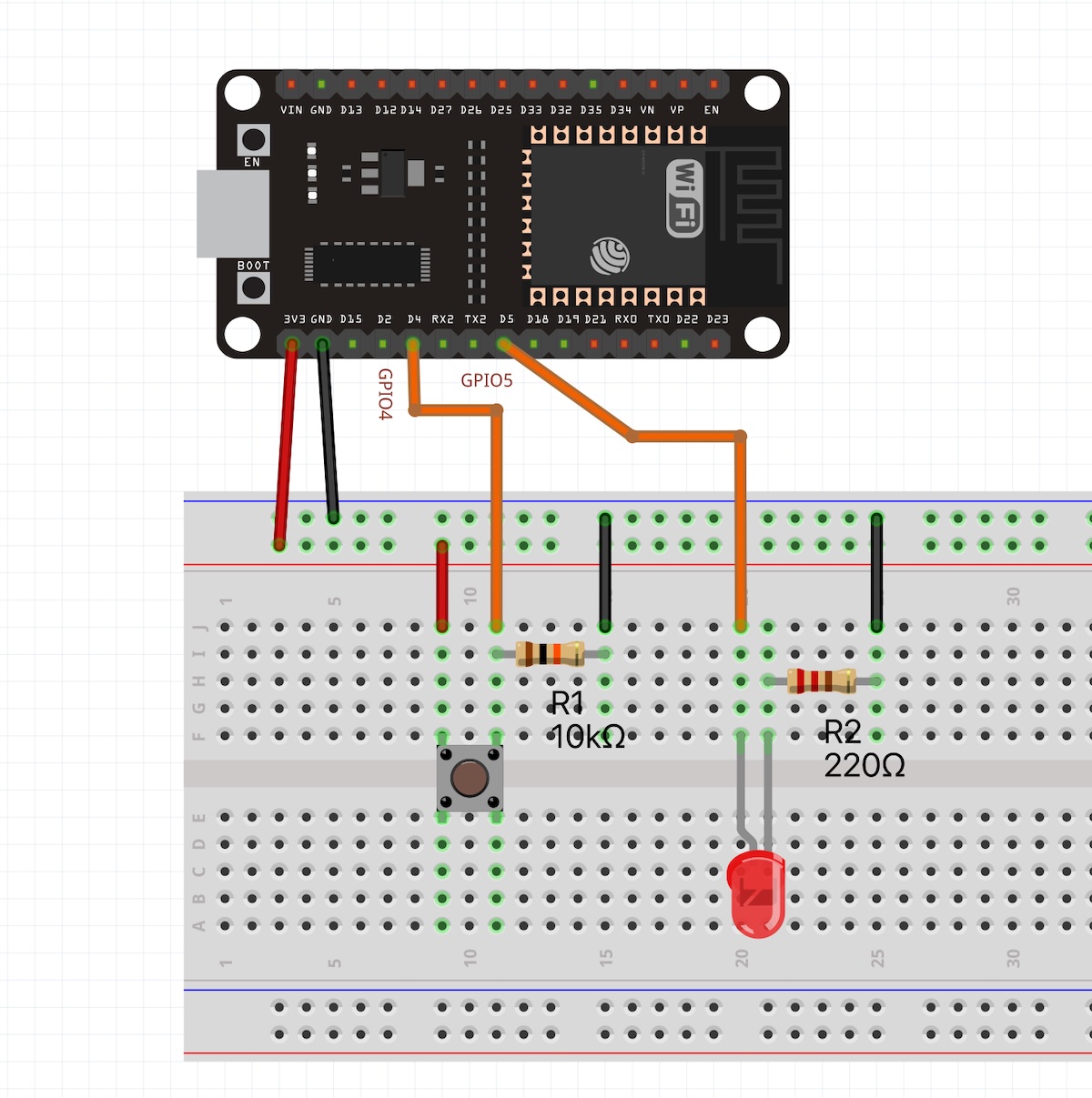
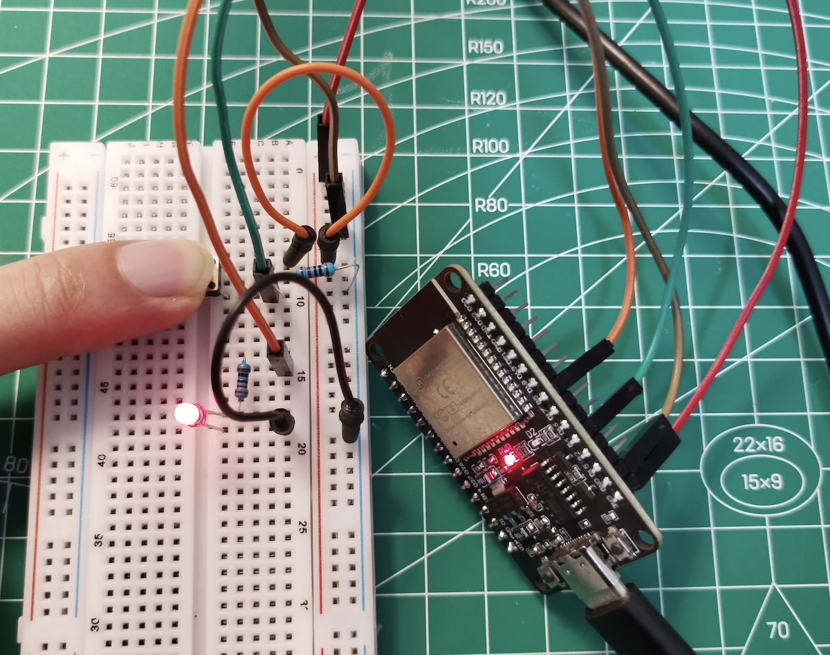
Assemble the circuit as shown in the schematic below:

Connections Overview
- The pushbutton is connected to GPIO 4 and GND, with a 10kΩ pull-down resistor to ensure a stable LOW signal when not pressed.
- The LED is connected to GPIO 5 through a 220Ω current-limiting resistor.
- The long leg (anode) of the LED connects to GPIO 5, and the short leg (cathode) goes to GND through the resistor.
Arduino Sketch
// Pin definitions
const int buttonPin = 4; // Pushbutton connected to GPIO 4 (with external pull-down resistor)
const int ledPin = 5; // External LED connected to GPIO 16

// Variable to store button state
int buttonState = 0;

void setup() {
	Serial.begin(115200); // Start serial communication for debugging
	// Configure button pin as input
	pinMode(buttonPin, INPUT);
	// Configure LED pin as output
	pinMode(ledPin, OUTPUT);
}

void loop() {
	// Read the pushbutton value
	buttonState = digitalRead(buttonPin);

	// Print the current button state to the Serial Monitor
	// (0 = not pressed, 1 = pressed)
	Serial.println(buttonState);

	// Control LED based on button state
	if (buttonState == HIGH) {
		digitalWrite(ledPin, HIGH); // Button pressed → turn LED ON
	} else {
	digitalWrite(ledPin, LOW); // Button not pressed → turn LED OFF
}
delay(100); // Small delay to debounce and avoid flooding the serial monitor
}How the Code Works
The ESP32 reads the state of the button using digitalRead() and then controls the LED using digitalWrite().
digitalRead(GPIO)
ReturnsHIGHorLOWdepending on the voltage at the pin.
digitalWrite(GPIO, STATE)
Sets the voltage at the pin toHIGH(3.3V) orLOW(0V), allowing us to turn devices on or off.
Uploading the Sketch
To upload the code to your ESP32:
- Connect your ESP32 to your computer via USB.
- Open the Arduino IDE.
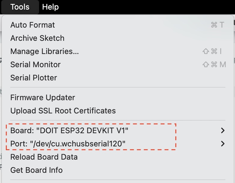
- Select the ESP32 board: Tools > Board > ESP32 Dev Module
- Select the correct port: Tools > Port > (Your ESP32 port)
5. Click the Upload button (✓ icon) to compile and upload the code.

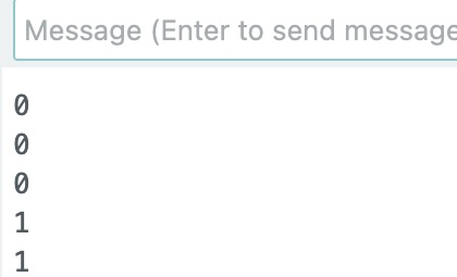
Once uploaded, open the Serial Monitor (115200 baud rate).
Press the button and observe how the LED responds — and how the button state is printed in real time.
Troubleshooting Tips
- Make sure your button is connected correctly and that the pull-down resistor is in place.
- If the LED doesn’t light up, double-check the polarity (the longer leg should be connected to the GPIO pin).
- Use the Serial Monitor to debug and check if the button state is being read correctly.
Conclusion
You’ve just completed a classic hardware interaction example using the ESP32: reading a button input and controlling an LED output. This pattern of input → logic → output is the foundation for many real-world electronics projects, from smart home devices to interactive sensors.
Next, you can try adding more buttons, using digitalWrite() to blink the LED, or combining this with sensors for more advanced experiments.
Getting Started with ESP32: Light Up an LED with a Pushbutton
Stay connected